This project is a beginner’s guide to assembling a DJI F450 drone step by step and understanding the basic mechanics of quadcopters. This guide covers all the steps needed to get a drone airborne. GPS guidance and FPV systems are not included here — those will be covered in more advanced guides.
⚠️ This tutorial was built with an APM 2.8 in 2025, which is officially unsupported by Mission Planner. It can be adapted with a more recent board such as a Pixhawk 2.1 or equivalent.
Bill of Materials
- F450 frame kit
- 4× 30 A ESCs
- 4× 2212 920kv brushless motors (2 CW and 2 CCW)
- 4× 1045 propellers
- Ardupilot APM 2.8 flight controller
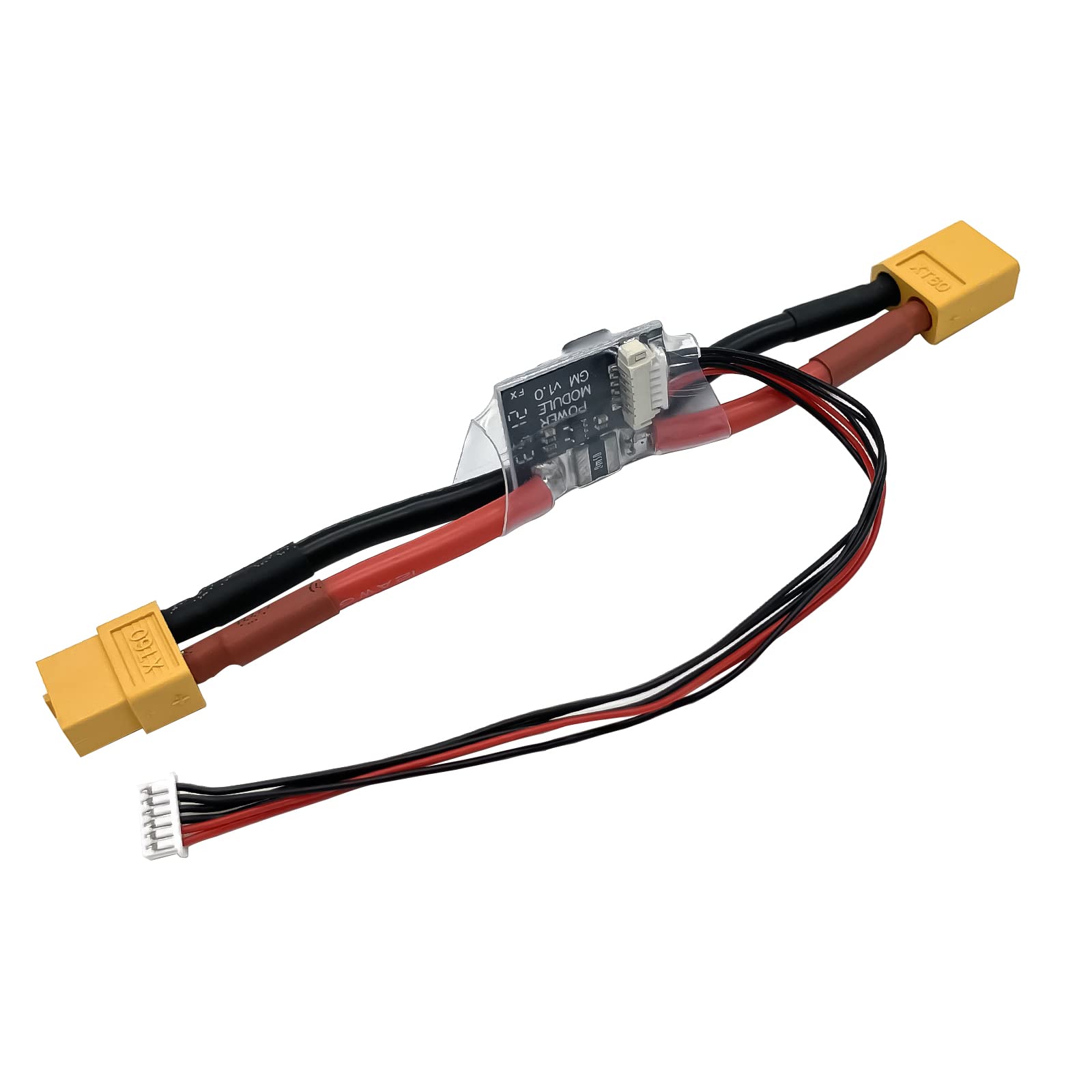
- Pixhawk/APM power module
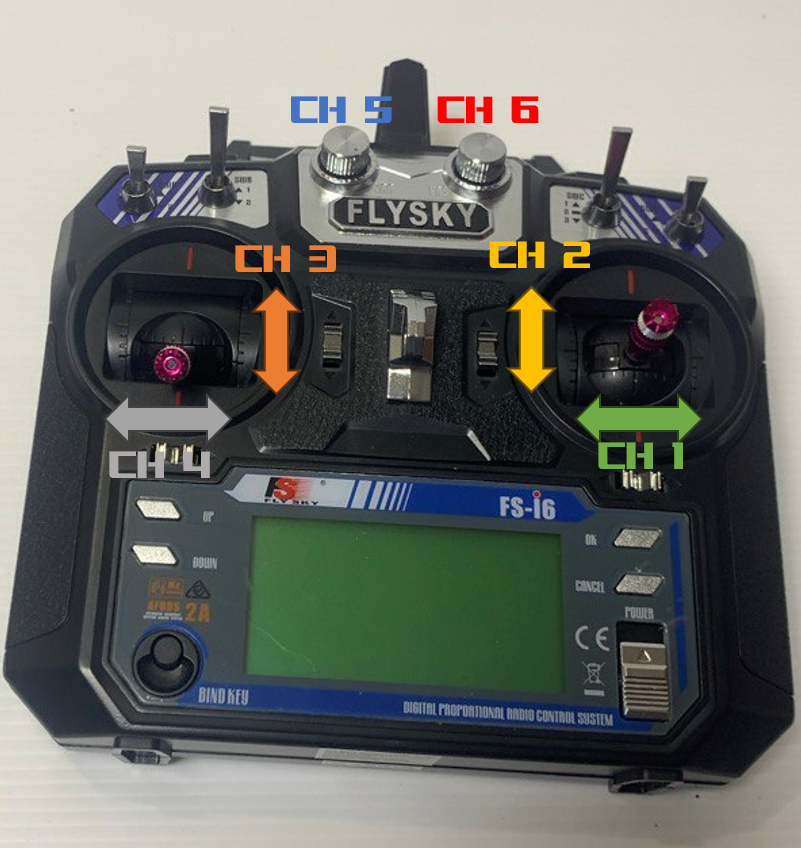
- FlySky FS-i6 transmitter
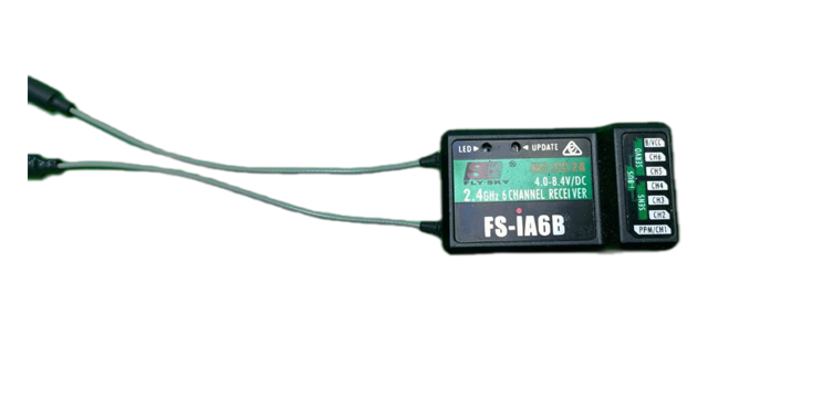
- FlySky iA6 receiver
- NEO 7M GPS module with compass
How It Works
A drone — more precisely a quadcopter — is a radio-controlled flying vehicle powered by 4 motors that keep it airborne. The motors are mounted on the 4 arms of the frame, each fitted with a propeller.
A quadcopter moves along 3 axes, known in aviation as:
- Roll
- Pitch
- Yaw
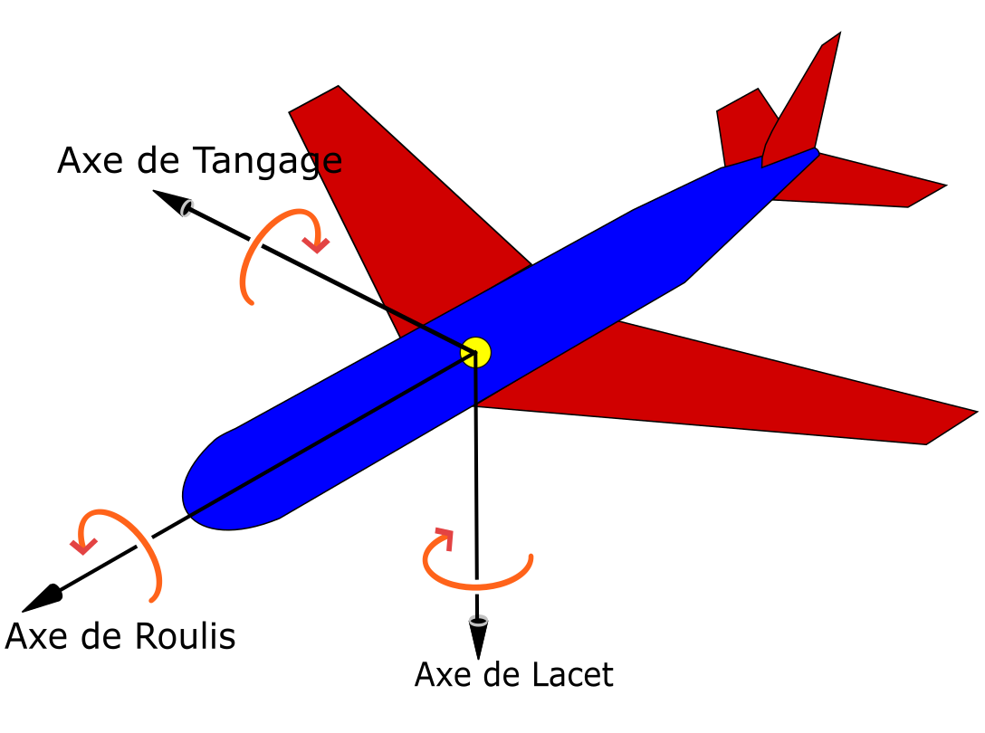
Movement around these 3 axes is made possible by the following sensors:
- Accelerometer — measures acceleration (in m/s² or g) along the X, Y and Z axes.
- Gyroscope — measures the angular velocity around each axis (X, Y, Z), typically in degrees per second (°/s) or radians per second.
A quadcopter uses 2 CW (Clockwise) and 2 CCW (Counter-Clockwise) motors. Their arrangement is critical and must follow a precise layout for the drone to fly correctly. ⚠️ It is equally essential to use the correct propellers for each motor direction (CW and CCW).
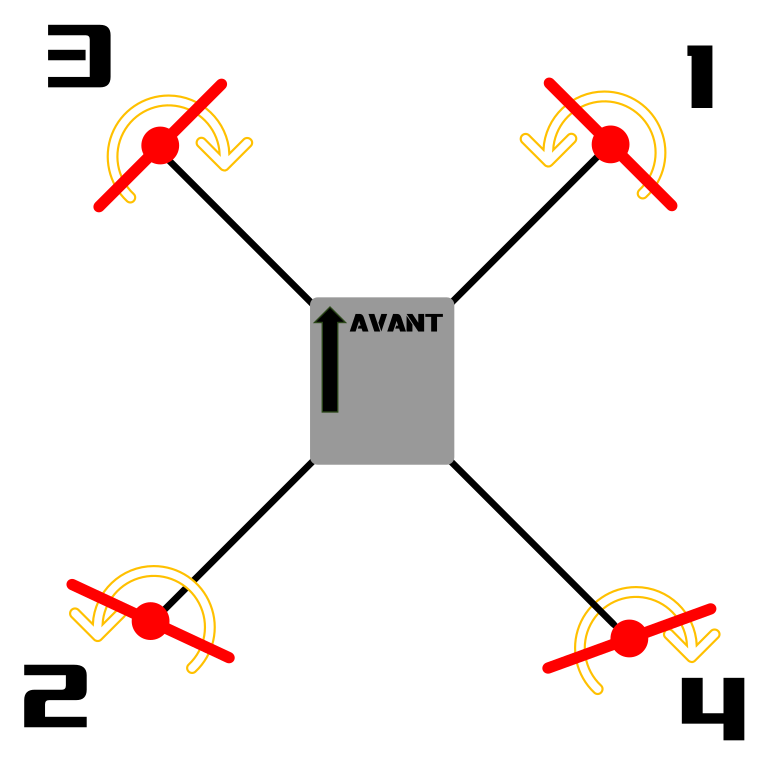
Drone movement results from varying each motor’s rotation speed. Example: to move forward, the front motors spin slightly slower than the rear motors, tilting the drone forward.
Lift is generated by two combined effects:
- Bernoulli’s principle (pressure difference) — the propeller’s airfoil shape creates lower pressure above and higher pressure below, generating an upward force.
- Newton’s third law (action-reaction) — the propeller pushes air downward; the equal and opposite reaction pushes the drone upward.
Component Overview
Frame
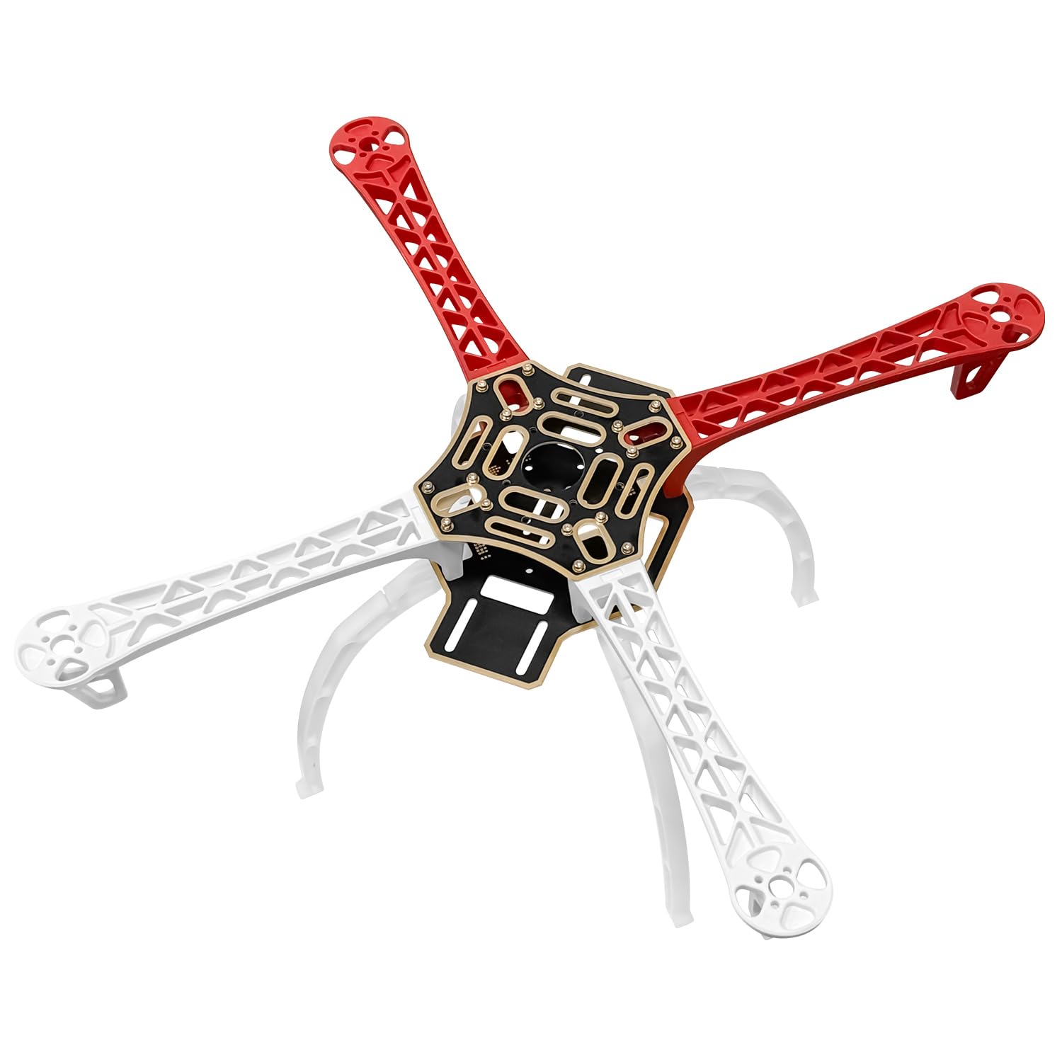
The frame holds all drone components together. It consists of 4 arms and a lower plate with integrated power distribution traces (+ and −), eliminating the need for a separate PDB.
ESC (30 A)
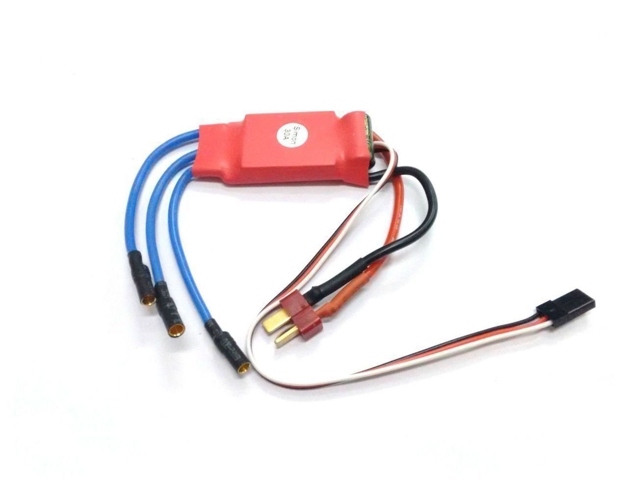
An ESC (Electronic Speed Controller) regulates speed, rotation direction, and braking of a brushless motor. It has three output wires because it drives the motor with three-phase current.
2212 920kv Brushless Motor (CW and CCW)
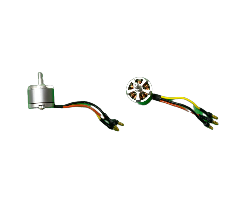
A brushless motor has no contact between the coils and magnets, resulting in a longer lifespan and less heat output. 1 Kv represents 1 RPM per volt, so:
Speed = 920 × 11.1 ≈ 10,212 RPM- Low KV (e.g. 920 KV) → more torque, larger propellers, stable flight, better endurance.
- High KV (e.g. 2300 KV) → higher speed, smaller propellers, reduced endurance.
The 2212 designation means: 22 mm stator diameter, 12 mm stator height.
1045 Propellers
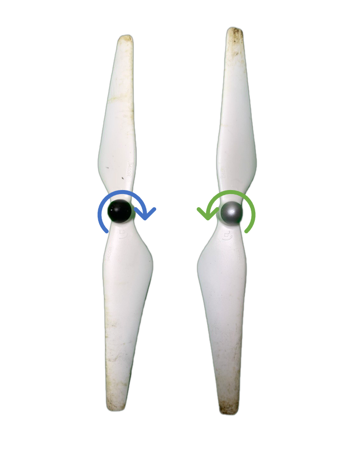
We use 1045 propellers, CW and CCW types, two of each rotation direction. The rotation direction can be identified by looking at which side is raised — the propeller always rotates in the same direction as its associated motor.
⚠️ Incorrect propeller placement can prevent takeoff or cause loss of control.
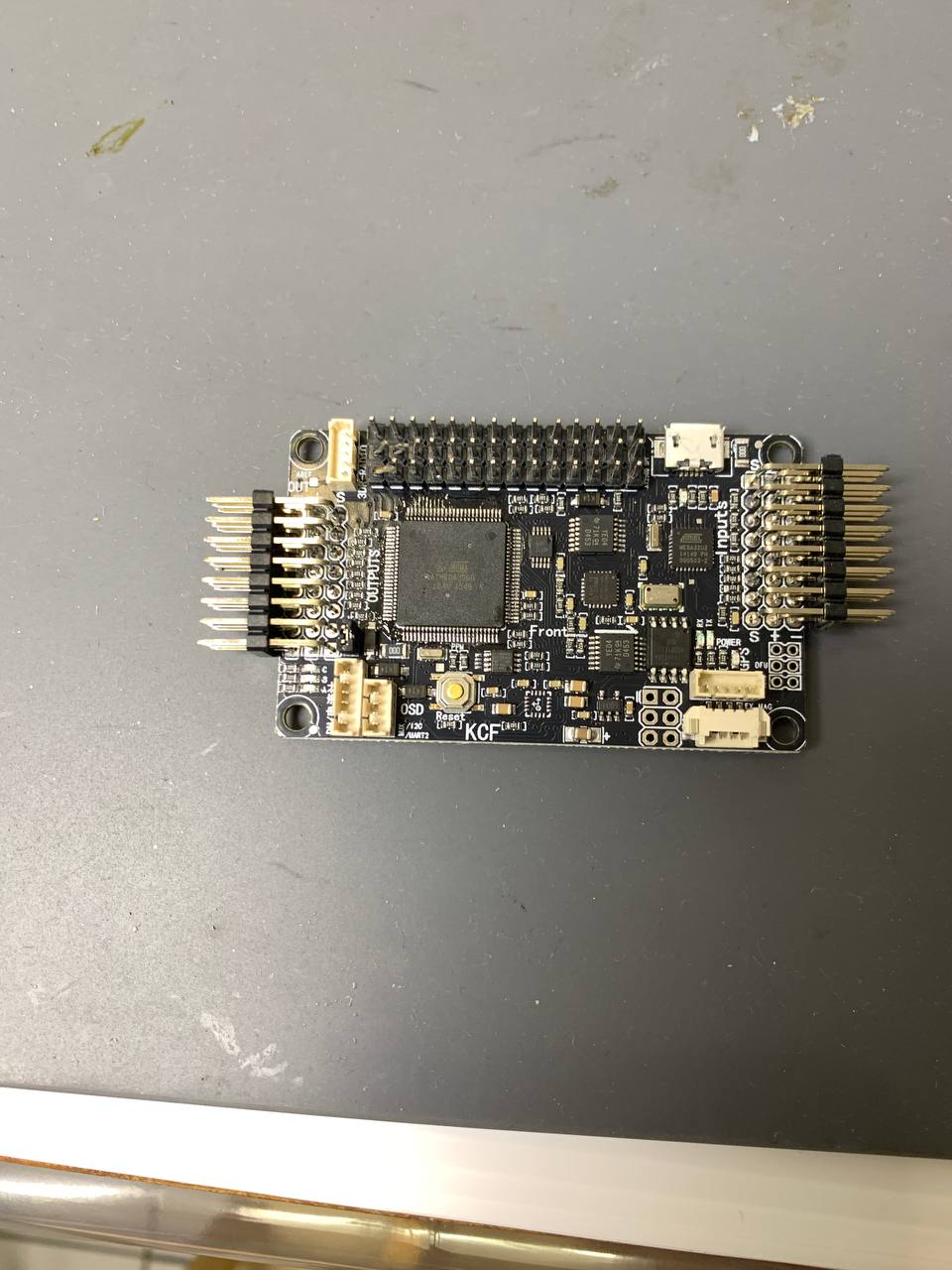
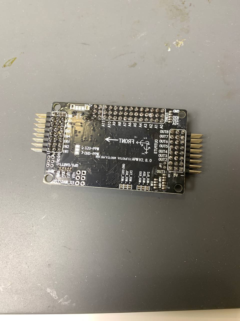
Flight Controller (APM 2.8)
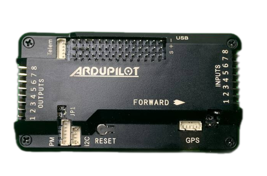
The flight controller is the brain of the drone. It receives transmitter commands, interprets them, and converts them into motor speeds.
⚠️ The APM 2.8 is obsolete — no firmware above version 3.3.0 can be installed on it.
Radio System
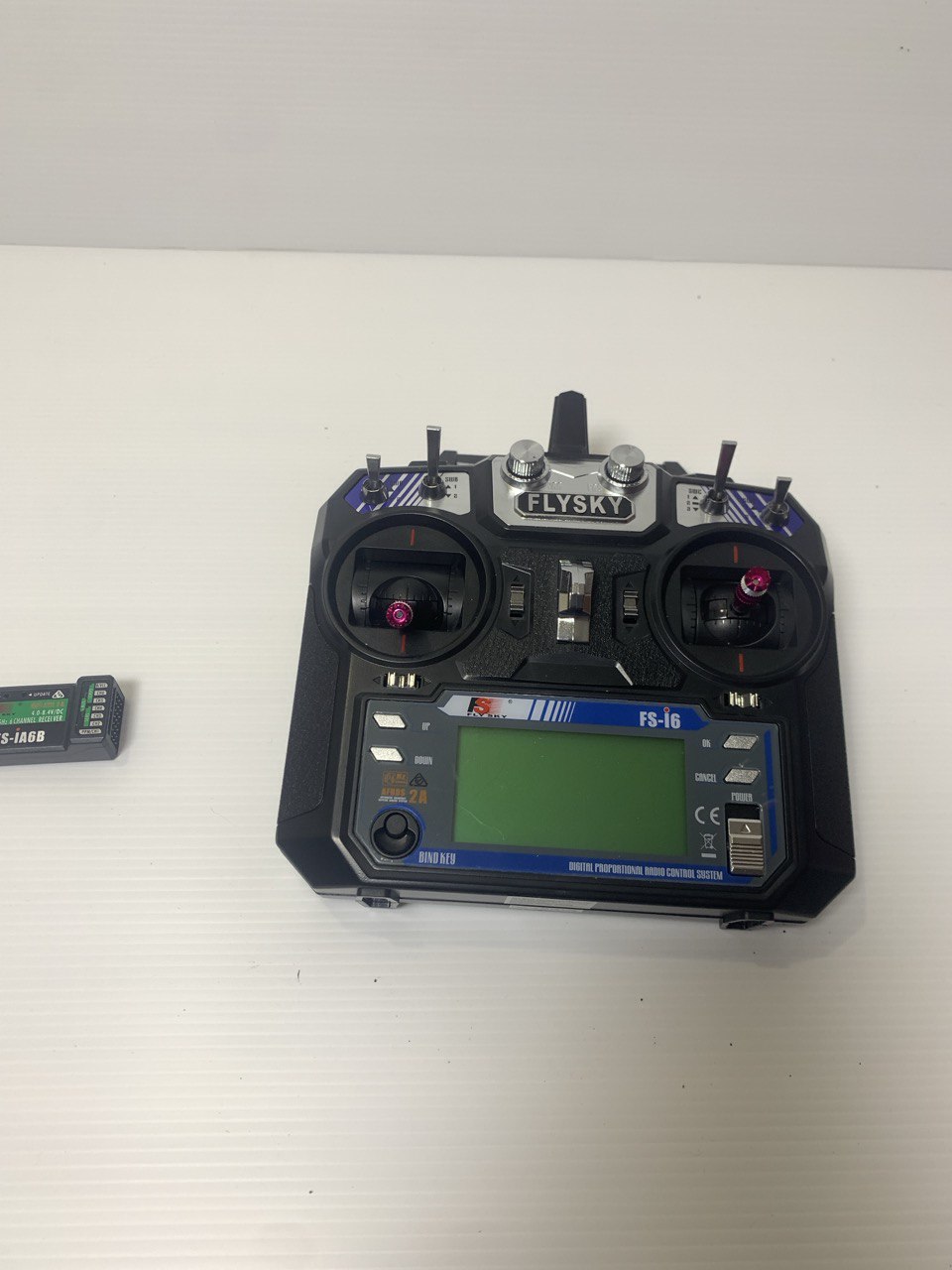
The radio system consists of a transmitter (used by the pilot) and a receiver on the drone. We use the FlySky FS-i6, with a range of approximately 1.5 km in open field on the 2.4 GHz band.
NEO 7M GPS Module with Compass
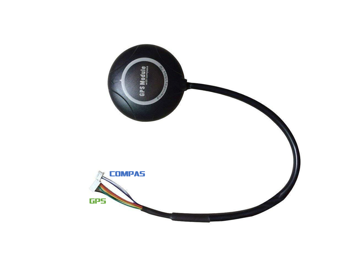
The GPS module determines the drone’s position by trilateration from satellite signals. The electronic compass (magnetometer) measures orientation relative to the Earth’s magnetic field on all three axes.
Power Module
The power module distributes battery energy to the entire drone. It supports up to 6S, powers the flight controller at 5.3 V / 3 A via the BEC connector, and can read battery voltage.
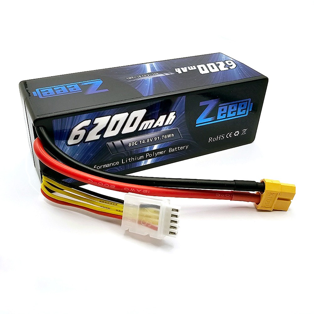
LiPo Battery 4S 6200 mAh
- 4S : 4 cells of 3.7 V in series → 14.8 V total.
- 6200 mAh : 6.2 Ah capacity.
⚠️ LiPo precautions: never discharge below 20%; limited number of charge/discharge cycles.
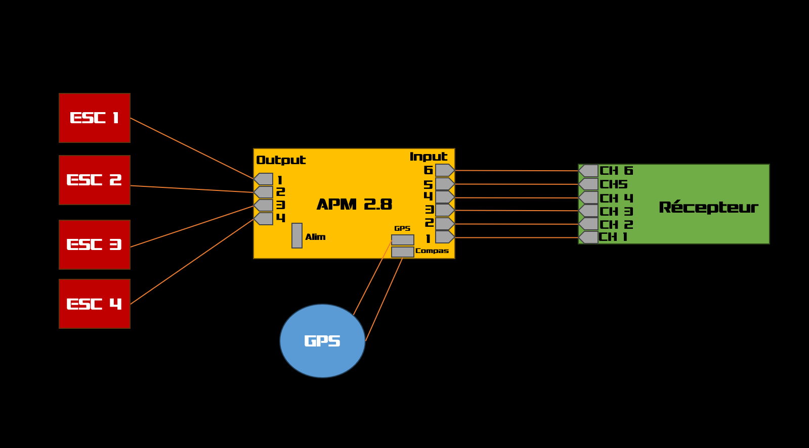
Wiring Diagram
Assembly
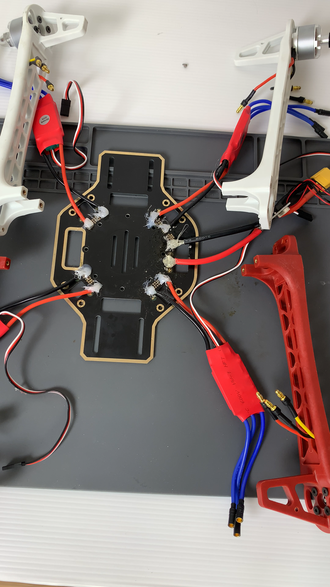
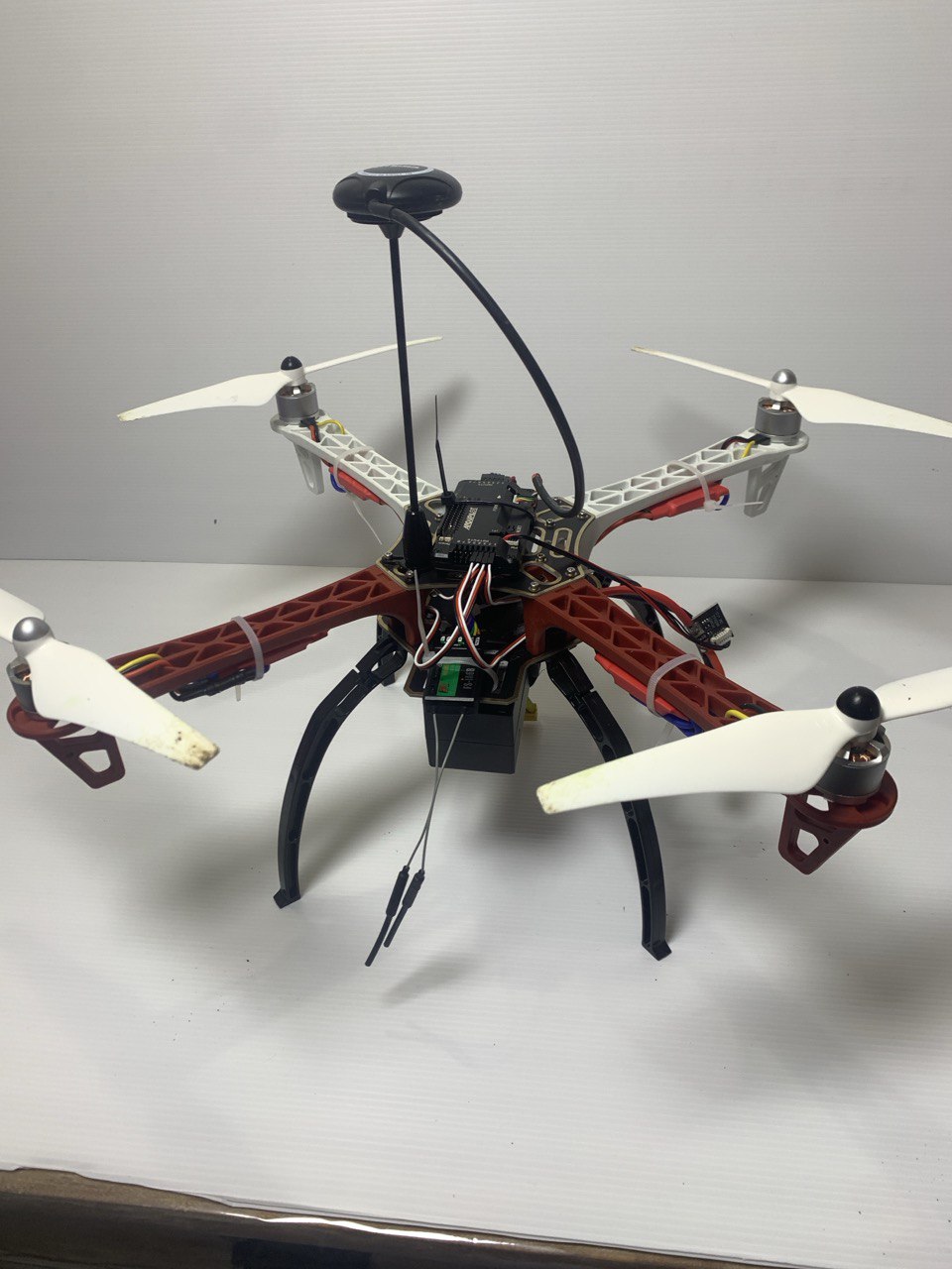
Start by soldering the ESCs to the bottom plate, on the + and − pads on each side, then solder the power module to its dedicated pads.
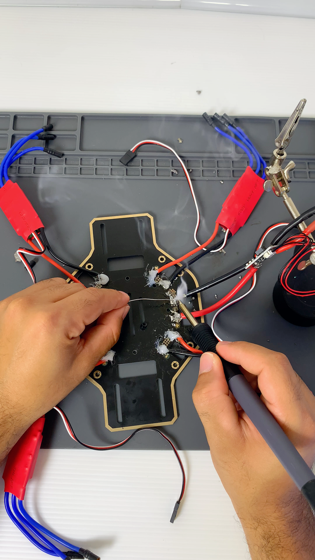
After soldering, insulate all exposed conductive areas (hot glue works well here).
Mount each motor on its arm.
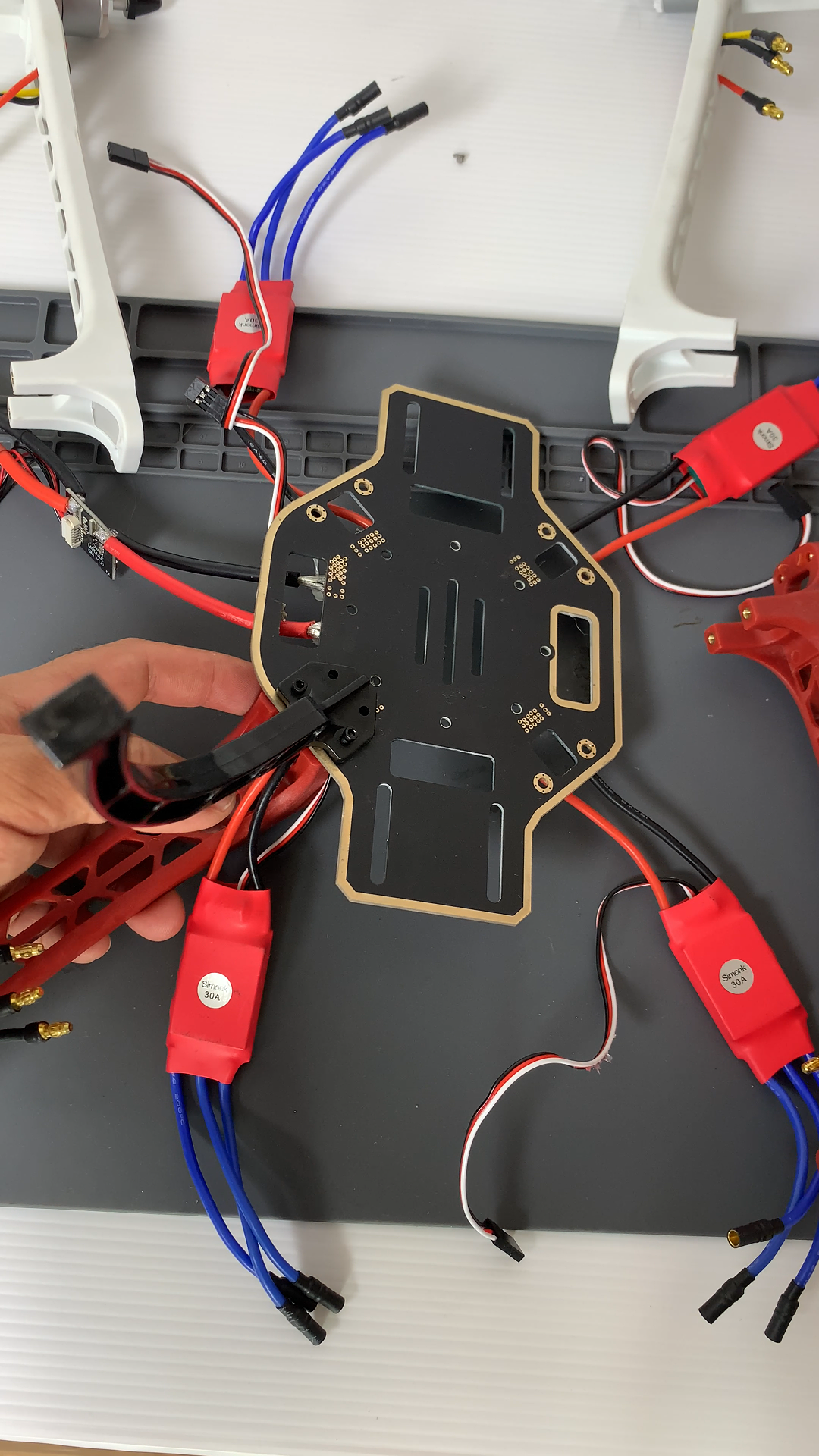
Attach the landing gear under the frame.
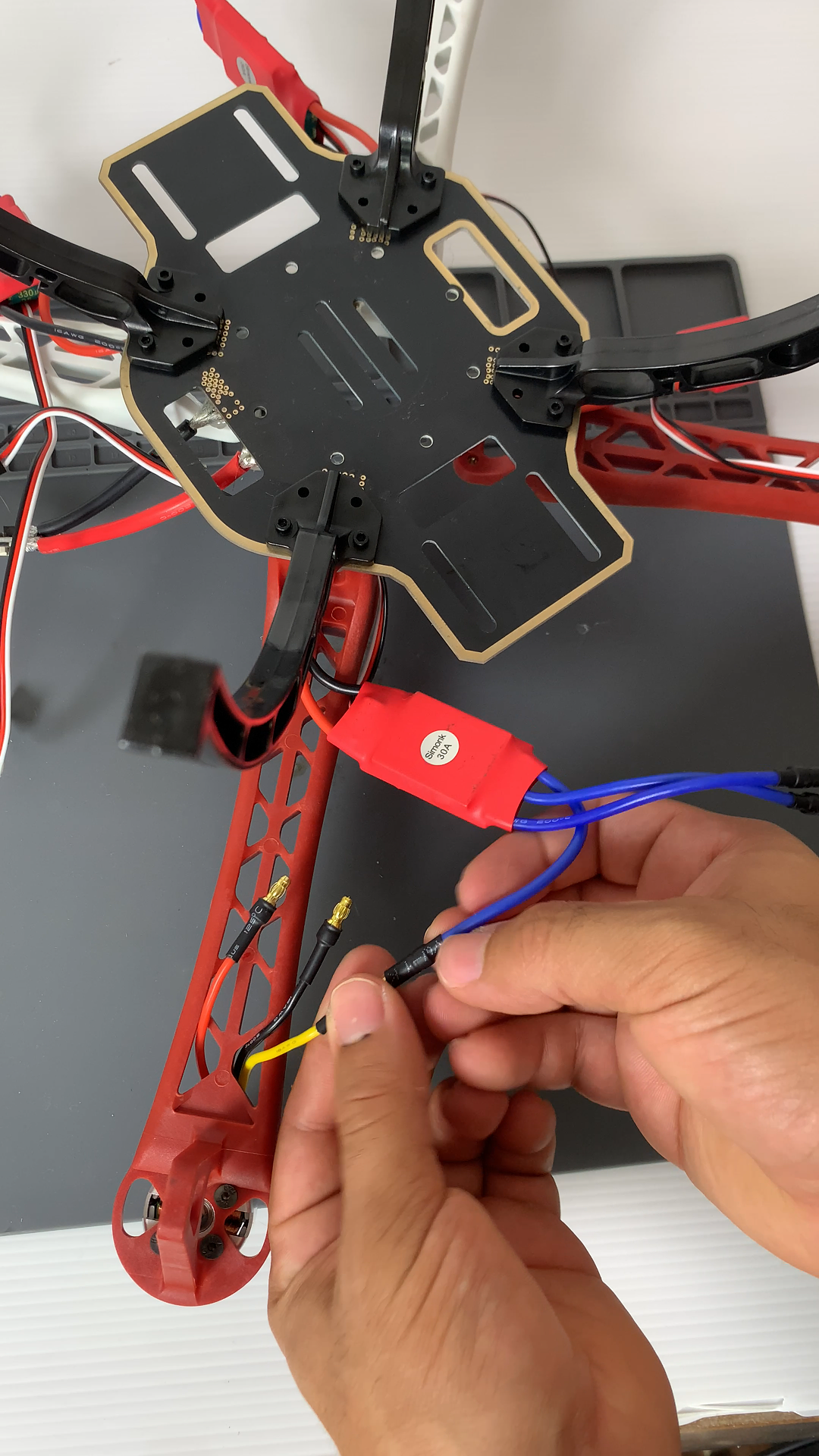
Connect the ESCs to the motors in any order — rotation direction will be verified later. To reverse a motor, swap any two wires between the ESC and motor.
Attach the top plate.
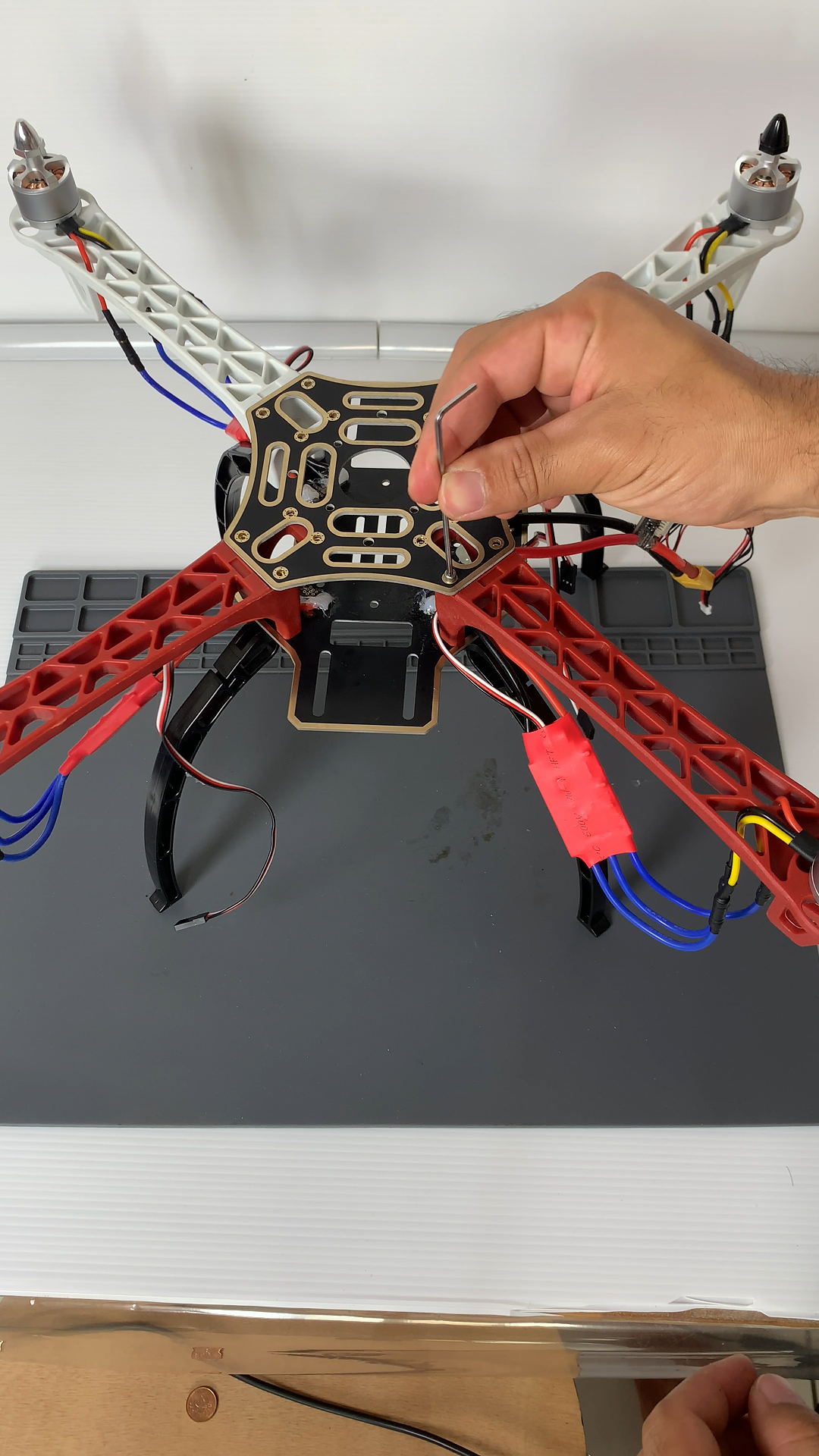
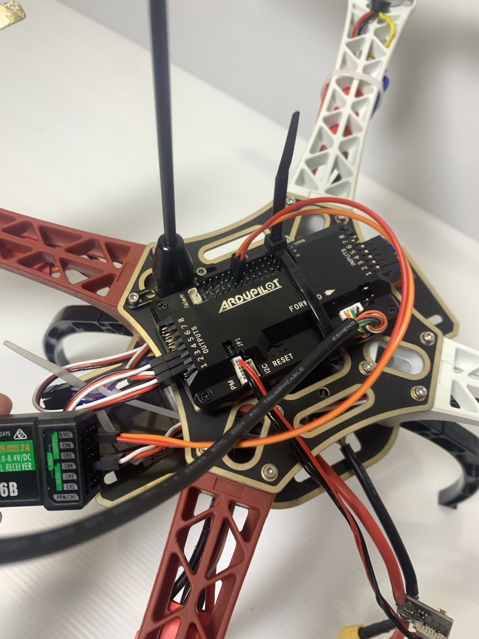
Mount the flight controller on top and secure ESCs and the receiver with zip ties.
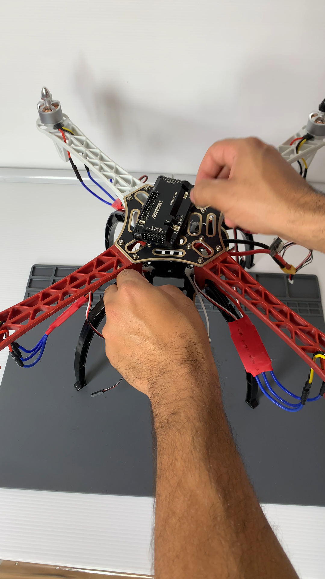
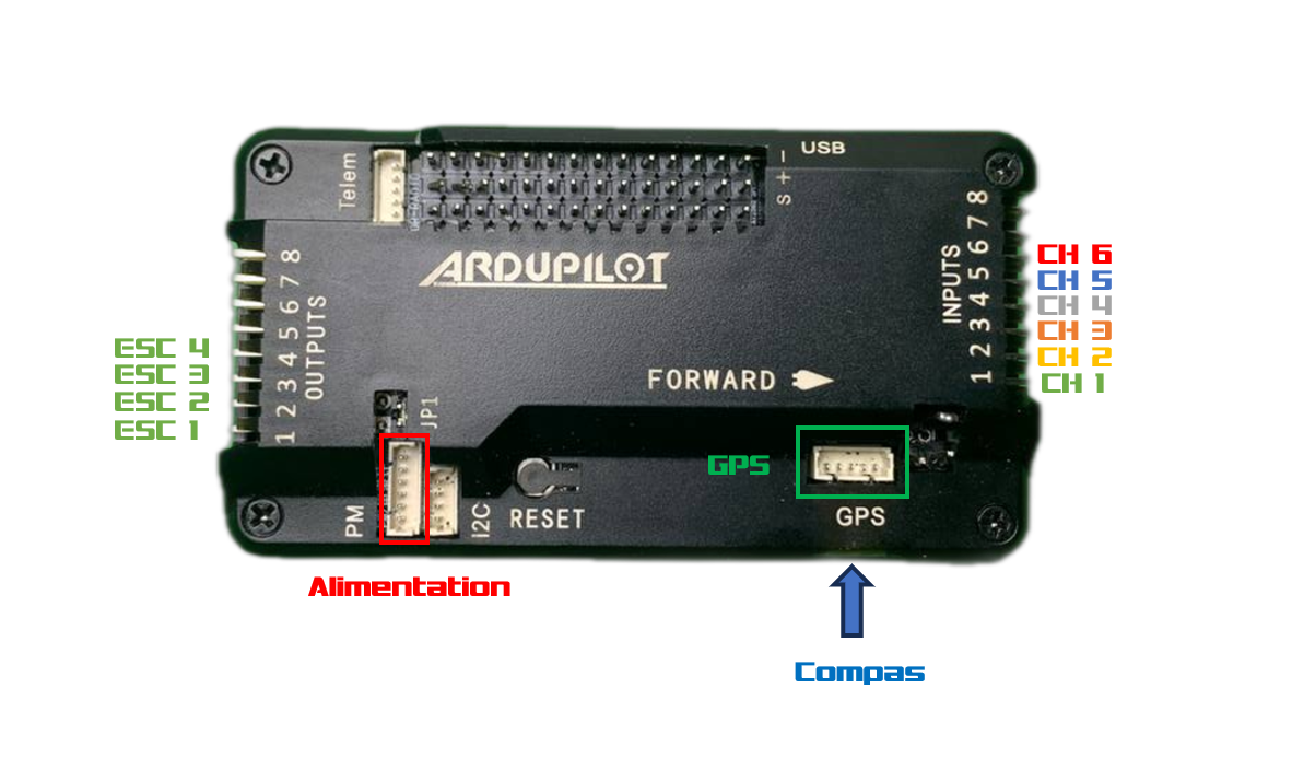
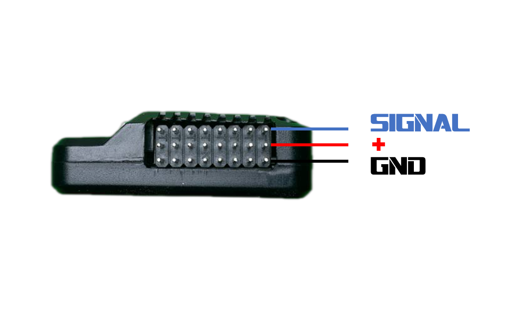
Attach the radio receiver and GPS mast to the frame. Connect the receiver to the APM Inputs pins, the power module to the PM port, and the GPS to the GPS and Compass connectors.
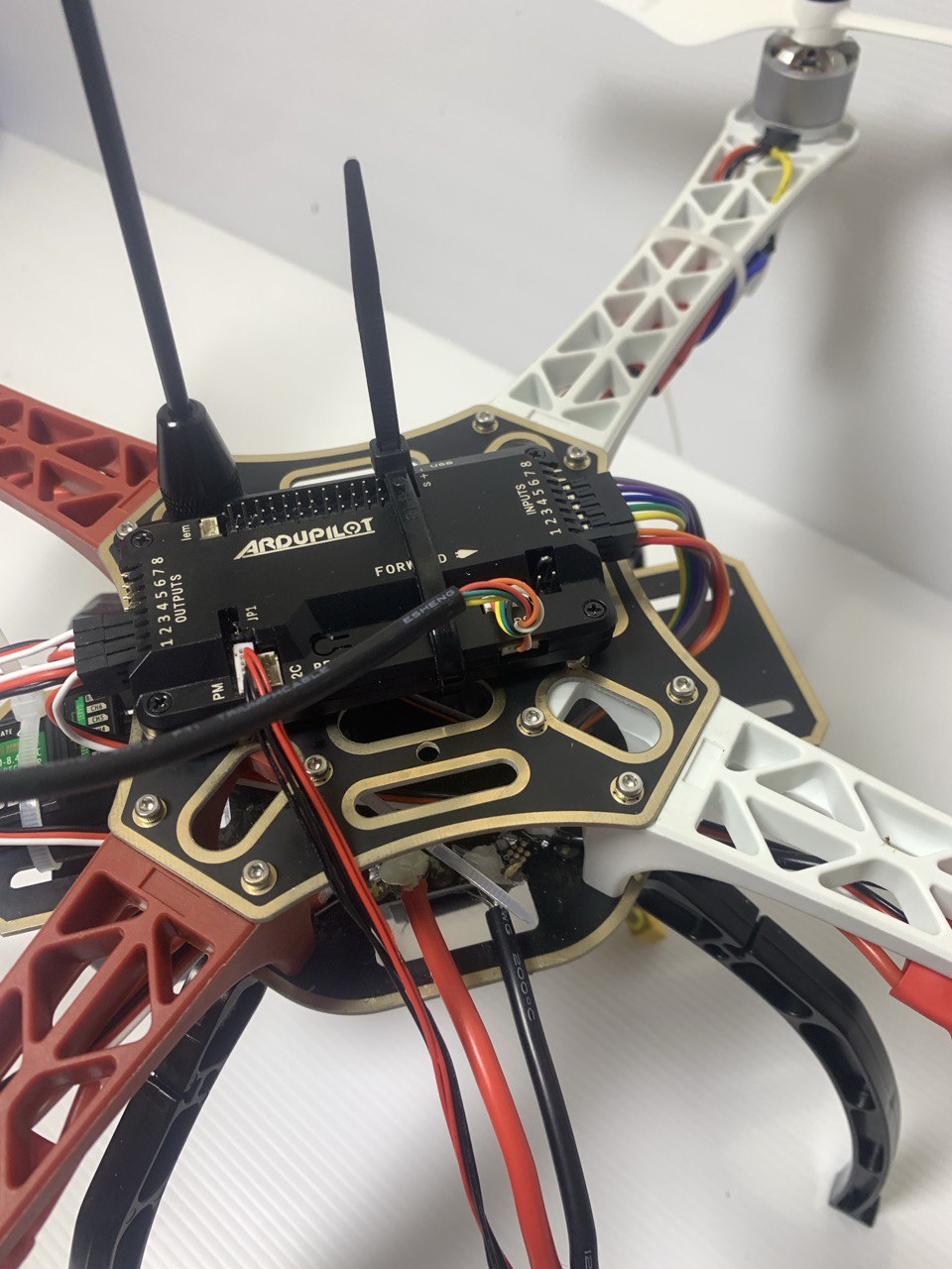
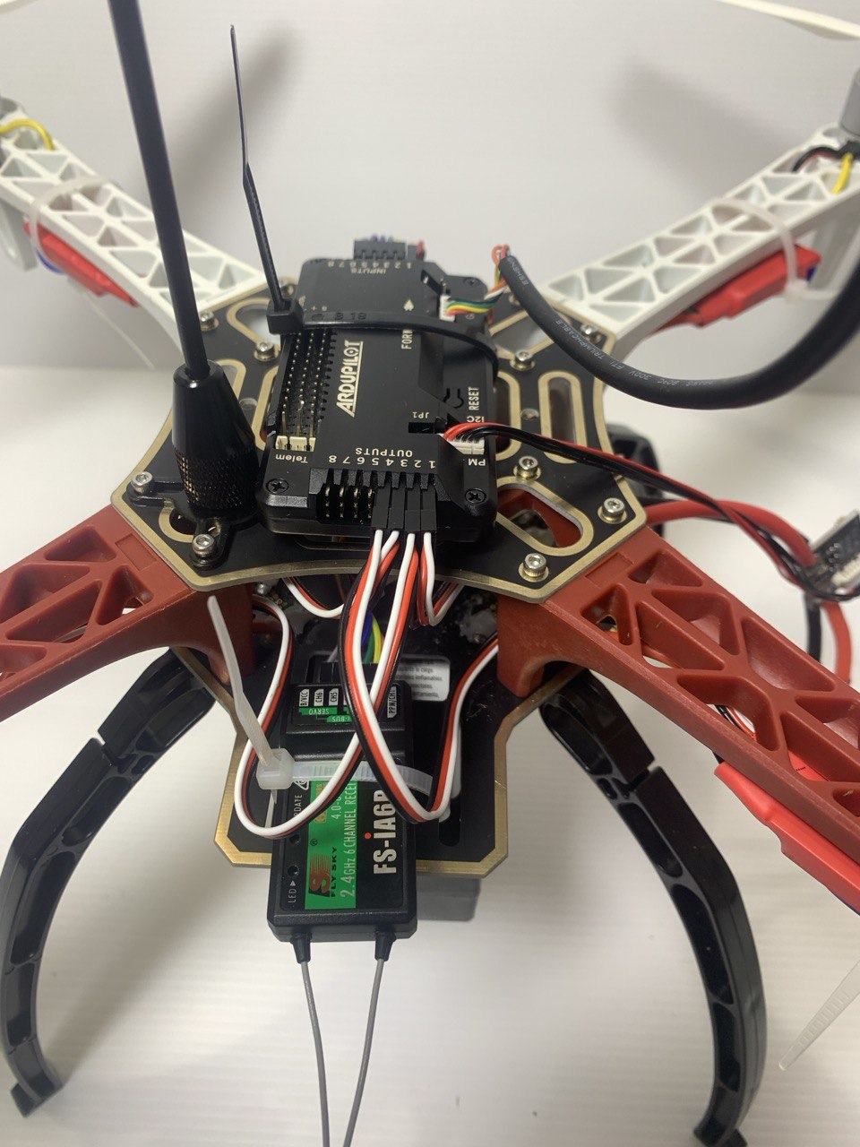
Connect the motors to the Outputs pins following the wiring diagram.
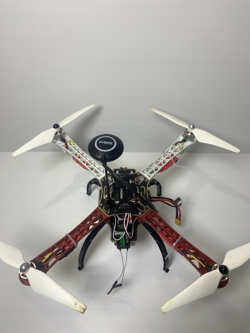
Mount the propellers.
Configuration & Calibration
Install Mission Planner on a computer and connect the drone via USB or telemetry module.
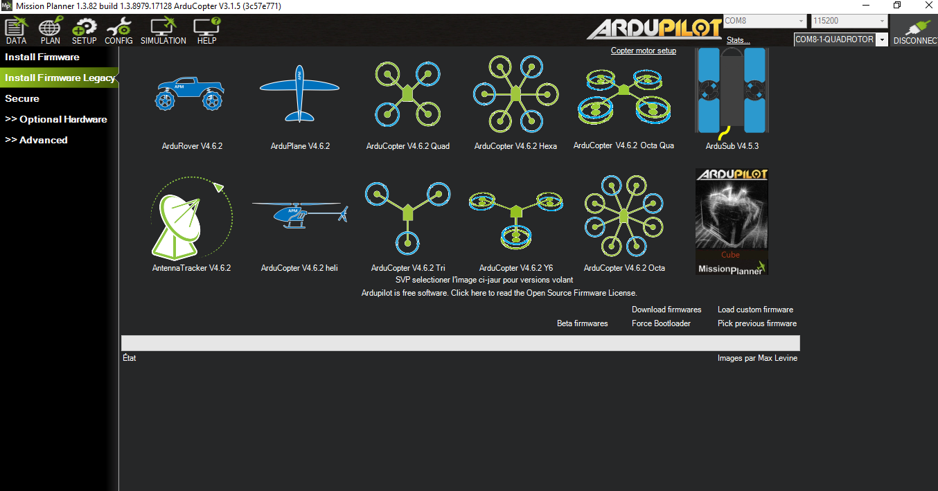
Firmware
The first step is to update the firmware — the software embedded in the flight controller.
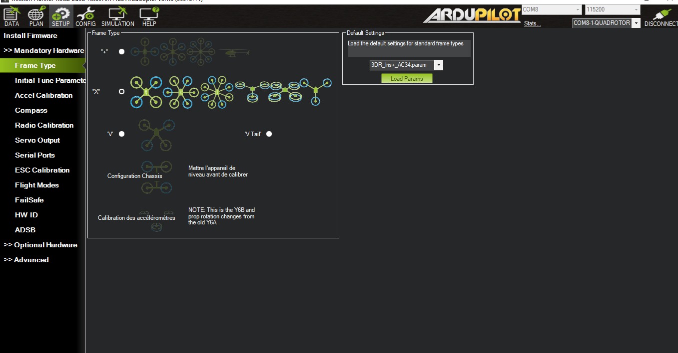
Select the frame type (quadcopter — already the default).
1 — Accelerometer
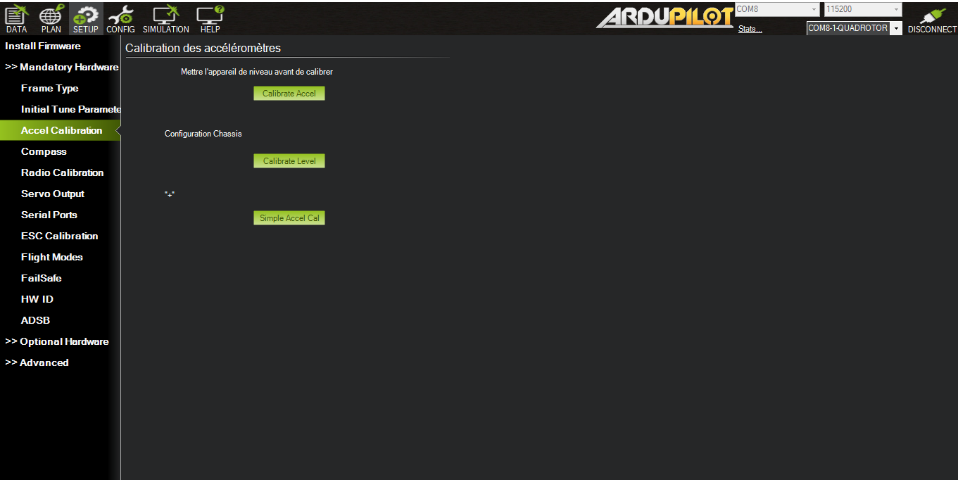
Click Calibrate Accel and follow the prompts: position the drone in each orientation shown (front, side, back, etc.).
⚠️ Ensure the drone is level before starting.
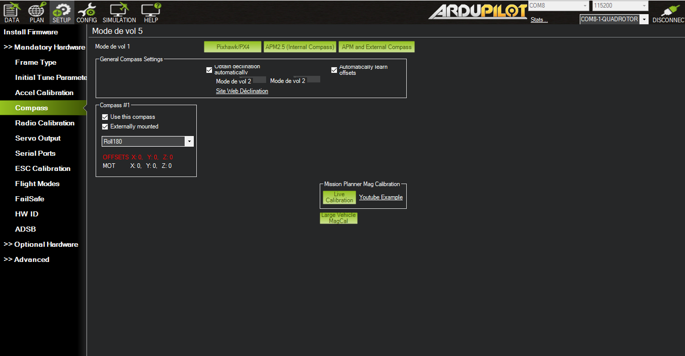
2 — Compass
Not required without GPS, but needed for RTL and autonomous missions.
Go to Mandatory Hardware > Compass, select APM and External Compass, then click Live Calibration.
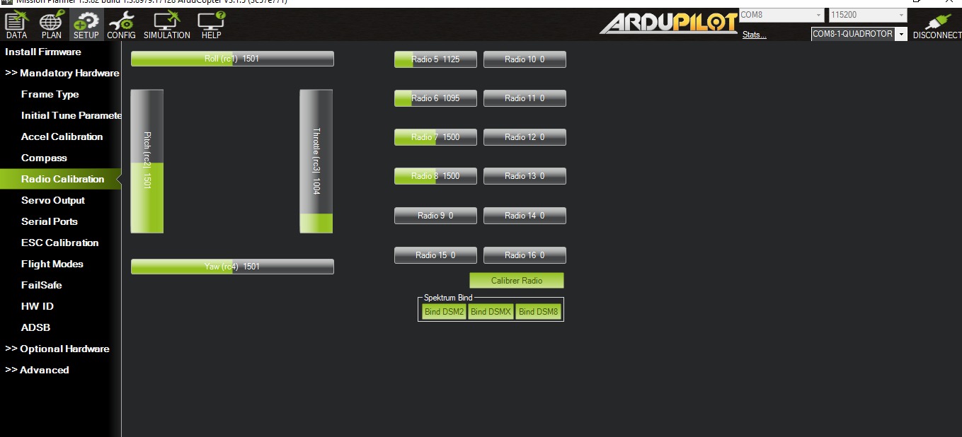
3 — Radio
Go to Mandatory Hardware > Radio Calibration. Make sure the receiver is bound to the transmitter before starting.
4 — Battery
Enable the Battery Monitor under Optional Hardware to protect the battery.
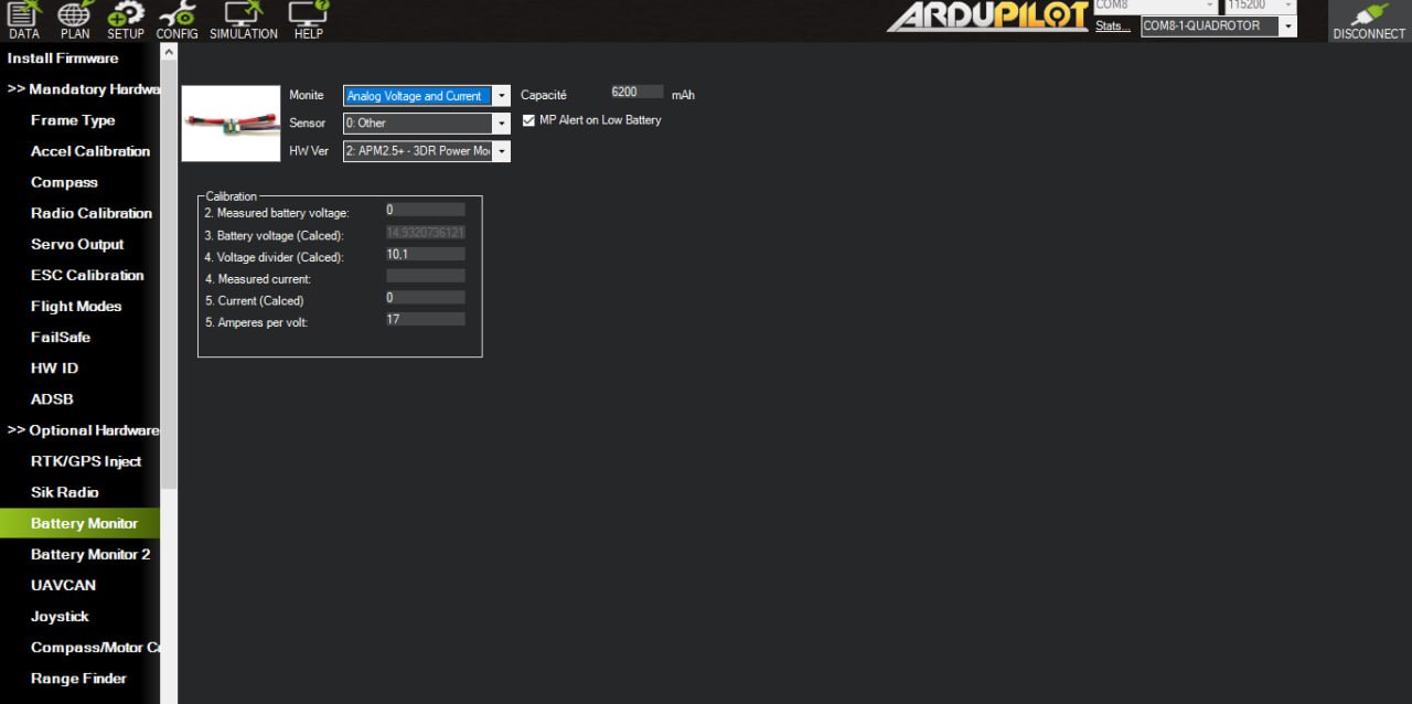
Reference voltages for a 4S battery:
- 100% : 16.8 V
- Empty (limit) : 12.8 V
- Recommended cutoff threshold : 13.8 V – 14 V
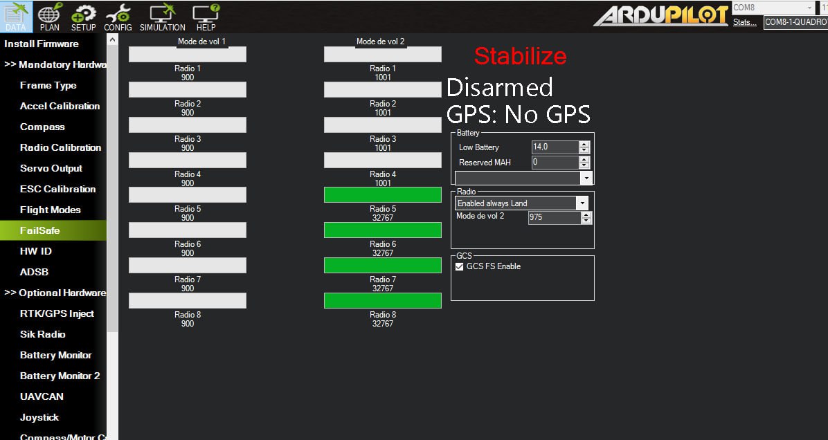
Enable FailSafe > Enabled Always Land so the drone lands automatically when voltage drops critically.
5 — ESCs
ESC calibration ensures all motors spin at matched speeds.
Manual calibration procedure:
- Connect the motor to pin 3 of the receiver.
- Connect one + / − pair from the ESC to the flight controller.
- Turn on the transmitter and push the left stick all the way up.
- Plug in the battery and wait for the ESC beep.
- Repeat for all ESCs.
First Flight
Connecting the Battery
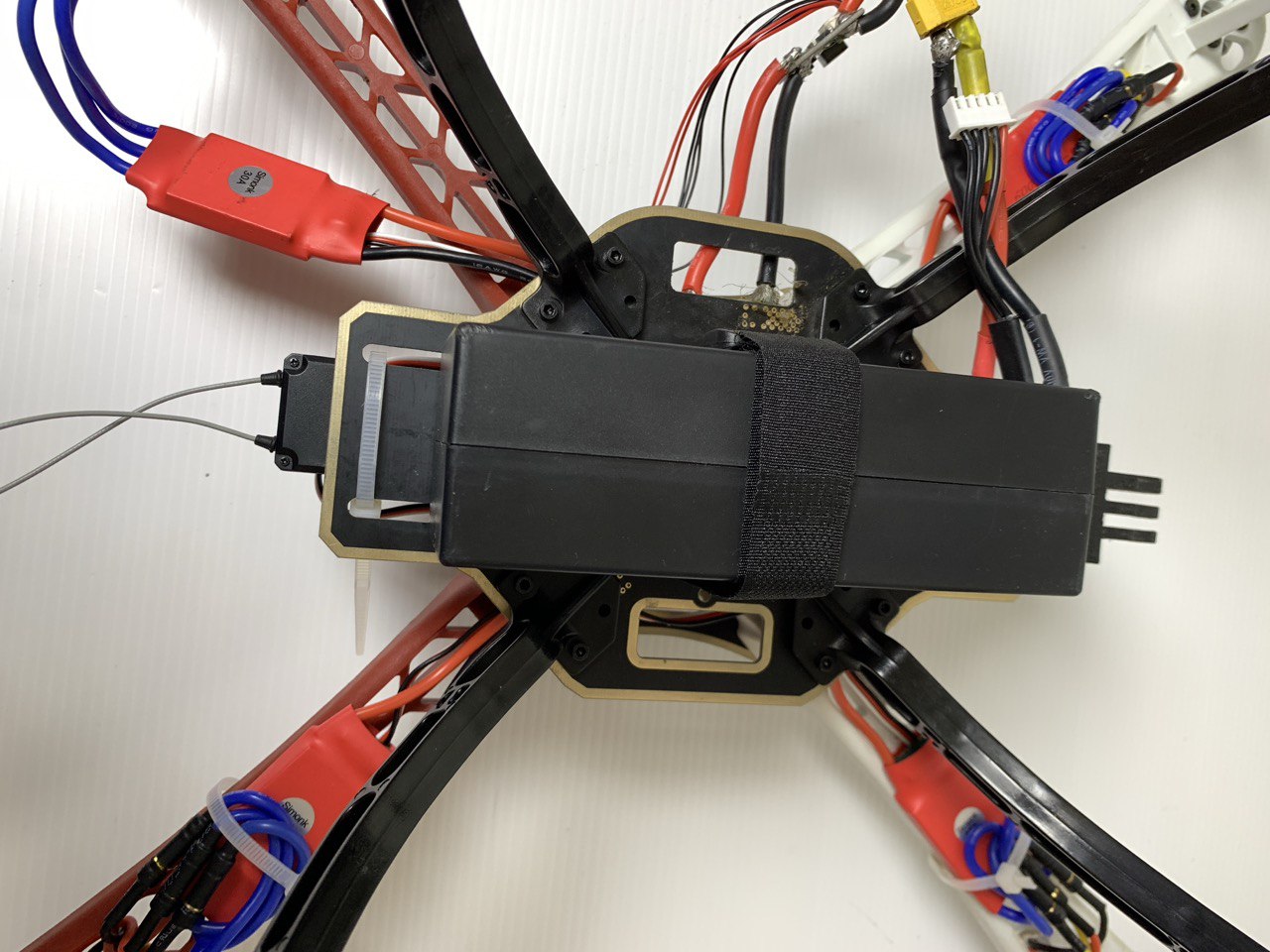
Connect the battery to the power module and secure it firmly to the frame.
Arming
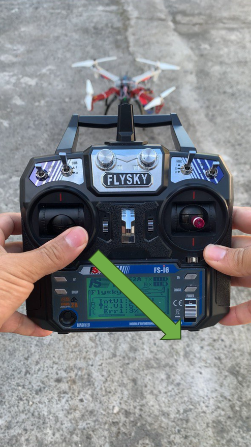
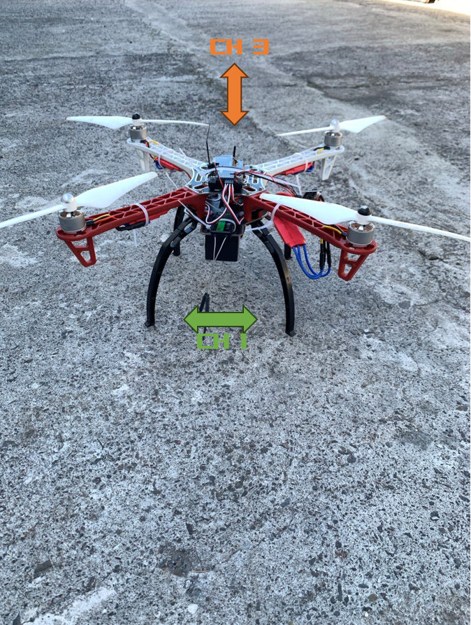
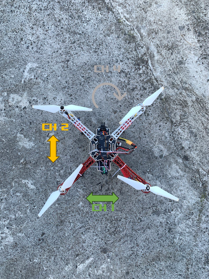
Hold the left stick down-right for a few seconds. If arming succeeds, motors start spinning at low throttle.
⚠️ If arming fails, see the Tips & Tricks section below.
Takeoff and Flight
Raise the left stick (CH3 — Throttle) to take off, then use the other channels to navigate.
Disarming
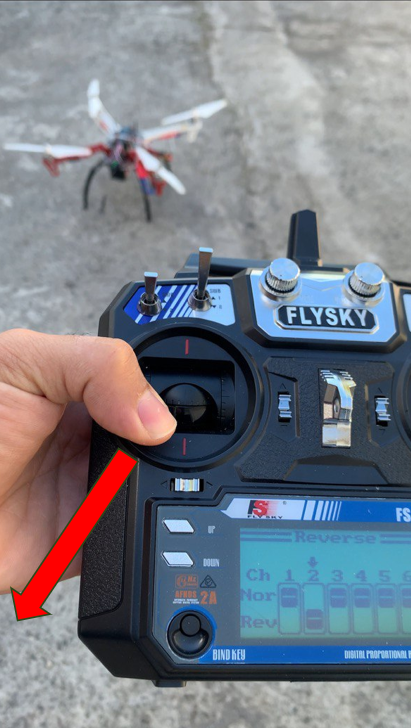
Hold the left stick down-left to disarm after landing.
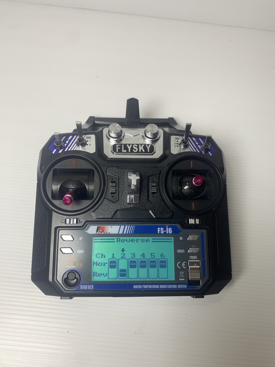
Reversing Channel 2
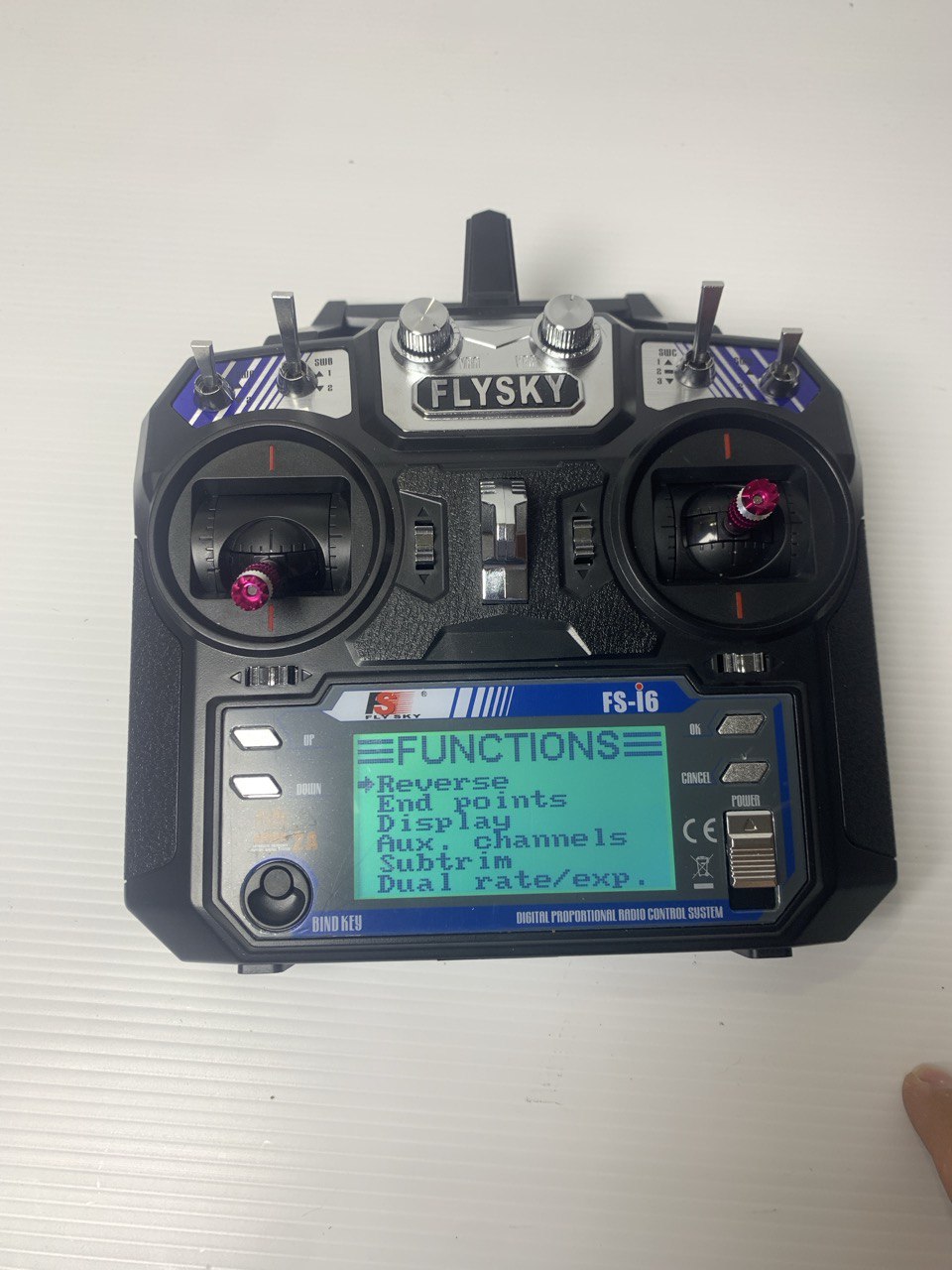
If the drone flies backward when you push forward, reverse CH2 in the transmitter settings:
- Hold OK.
- Go to Functions Setup via the Down arrow then OK.
- Press OK on the Reverse function.
- Move the cursor to CH2 with OK.
- Press Down to apply the reverse.
Tips & Tricks
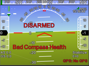
Error: Bad compass health
The compass is not being detected. Two solutions:
- Use a GPS module with integrated compass and select External Compass.
- Use the APM’s internal compass → solder jumper pins 2 and 4.
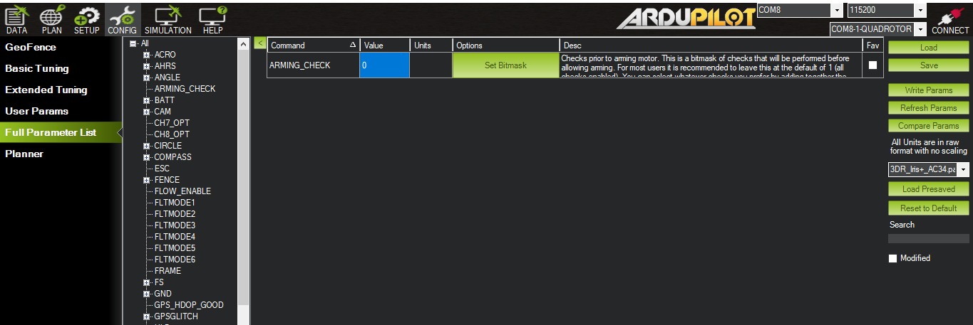
Arming fails due to GPS pre-arm check
Disable pre-arm checks: Full Parameter List > ARMING_CHECK → set to 0.
⚠️ Click Write Params for the change to take effect.
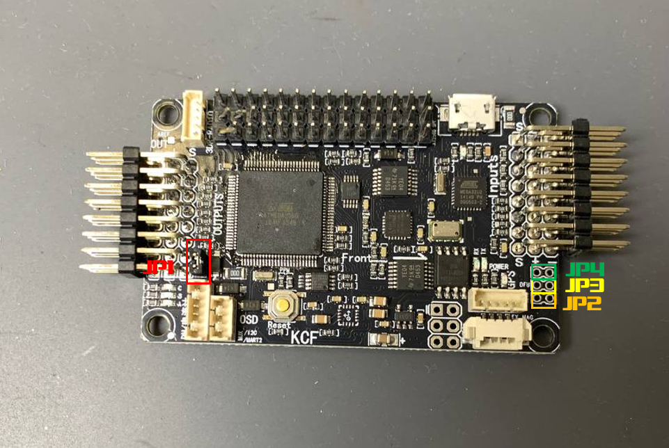
APM Flight Controller Jumpers
- Jumper 1 : required for power.
- Jumper 2 (MAG) : solder to use the internal compass.
- Jumper 3 (DFU) : DFU mode for bootloader flashing.
- Jumper 4 : solder to use an external compass.